 .
.
Here we describe the hardware in REMEMOTECH :-
The normal Memotech memory map is implemented. As far as the CPU is concerned, it believes it has :-
The Altera DE1 has 4MB of Flash, 512KB of SRAM and 8MB of SDRAM.
During normal operation, what the CPU sees as ROM and RAM is provided by SRAM. The astute reader will note that 8KB+8x8KB+64KB+320KB is less than 512KB. In the remaining SRAM space sits REMON (8KB) and the read/write virtual cassette data space (48KB).
The FPGA also contains 1KB of on-chip ROM which contains a program called REBOOT.
In these pictures, ROMs are shown with their names and are 8KB in size and RAM pages are assigned letters and are 16KB in size. RAM pages α to δ are the normal 64KB present in an MTX512. RAM pages a to t are extra pages, which are used as 320KB of RAM Disc.
REMEMOTECH logical memory map, as seen in RELCPMH=0 mode :-
| R2,R1,R0 | 0x0000..0x1fff | 0x2000..0x3fff | 0x4000..0x7fff | 0x8000..0xbfff | 0xc000..0xffff | P3,P2,P1,P0 |
|---|---|---|---|---|---|---|
| 0 | OS | BASIC | γ | β | α | 0 |
| 1 | ASSEM | a | δ | 1 | ||
| 2 | ROM 2 | c | b | 2 | ||
| 3 | ROM 3 | e | d | 3 | ||
| 4 | CP/M boot | g | f | 4 | ||
| 5 | SDX ROM | i | h | 5 | ||
| 6 | ROM 6 | k | j | 6 | ||
| 7 | ROM 7 | m | l | 7 | ||
| o | n | 8 | ||||
| q | p | 9 | ||||
| s | r | A | ||||
| t | B | |||||
| C | ||||||
| D | ||||||
| any SRAM | any SRAM | E | ||||
| any SRAM | any Flash | F | ||||
REMEMOTECH logical memory map, as seen in RELCPMH=1 mode :-
| 0x0000..0x3fff | 0x4000..0x7fff | 0x8000..0xbfff | 0xc000..0xffff | P3,P2,P1,P0 |
|---|---|---|---|---|
| δ | γ | β | α | 0 |
| a | b | c | 1 | |
| d | e | f | 2 | |
| g | h | i | 3 | |
| j | k | l | 4 | |
| m | n | o | 5 | |
| p | q | r | 6 | |
| s | t | 7 | ||
| 8 | ||||
| 9 | ||||
| A | ||||
| B | ||||
| C | ||||
| D | ||||
| E | ||||
| on-chip ROM | any SRAM | any Flash | F |
The on-chip memory is only 1KB in size, and so repeats 16 times.
The IOBYTE register is initialised to 0x8f on reset,
so as to ensure execution starts from the on-chip memory.
In RAM pages 14 and 15, it is possible to address any 16KB page of SRAM or Flash.
Which page is visible at 0x4000..0x7fff is controlled by page
register 1 (port 0xd0), and
which page is visible at 0x8000..0xbfff is controlled by page
register 2 (port 0xd1).
Just write the SRAM page number (range 0x00..0x1f) to the page register.
REMEMOTECH SRAM physical memory map (as a set of 16KB pages) :-
| SRAM address | SRAM page(s) | Content |
|---|---|---|
| 0x00000..0x0ffff | 0x00..0x03 | RAM pages α to δ |
| 0x10000..0x13fff | 0x04 | BASIC and ASSEM |
| 0x14000..0x17fff | 0x05 | ROM 2 and ROM 3 |
| 0x18000..0x1bfff | 0x06 | CP/M boot and SDX ROM |
| 0x1c000..0x1ffff | 0x07 | ROM 6 and ROM 7 |
| 0x20000..0x23fff | 0x08 | OS and REMON |
| 0x24000..0x2ffff | 0x09..0x0b | read/write virtual cassette area |
| 0x30000..0x7ffff | 0x0c..0x1f | RAM pages a to t, RAM Disc area |
Addresses 0x10000..0x7ffff of the REMEMOTECH Flash physical
memory map exactly matches the SRAM physical memory map.
0x00000..0x0ffff of the Flash isn't used as we don't initialise
the MTX512 RAM, only ROM images and Initial RAM Disc (pages a to t).
The first 64KB of the Flash chip has 8x8KB sectors and the rest of the
Flash is arranged in 64KB sectors - as we don't use the first 64KB,
we don't need any special case code for this.
Addresses 0x10000..0x7ffff on the "Flash image" SD Card are
copied to 0x10000..0x7ffff in Flash during initial setup, and
then from there to 0x10000..0x7ffff in SRAM during first startup
(if you press the right combination of keys on the DE1).
Addresses 0x80000 and above in the Flash are divided into
56 64KB virtual tape slots.
As these are flash, they are read-only to MTX BASIC.
ROM 2 support
REMEMOTECH r3 supports a daughter board, with an EEPROM/EPROM socket. If SW1 or SW1 are turned on, LEDR1 and the LED on the daughter card light up, and the socket is enabled.
Due to variations in device pinouts, the SW1 and SW0 switches must be used to select the device pinout and size :-
| SW1 | SW0 | Pinout | Size | Subpages |
|---|---|---|---|---|
| 0 | 0 | Socket not used | ||
| 0 | 1 | 2764 | 8KB | 1 |
| 27128 | 16KB | 2 | ||
| 1 | 0 | 27256 | 32KB | 4 |
| 1 | 1 | 27512 | 64KB | 8 |
When the socket is enabled, the chip contents appear as sub-pages in ROM slot 2. When disabled, whatever was loaded into SRAM by the initial flash setup is present.
Different chips have varying timing constraints, eg:
| Chip | Chip enable to data ready | Address valid to data ready | Output enable to data ready |
|---|---|---|---|
| ST M2764A-25 | 250ns | 250ns | 100ns |
| W27C512-12 | 120ns | 120ns | 55ns |
| W27C512-90 | 90ns | 90ns | 40ns |
| W27C512-70 | 70ns | 70ns | 30ns |
| W27C512-45 | 45ns | 45ns | 20ns |
As REMEMOTECH runs a T80 in FastZ80 mode, chip enable and address are
asserted ~2T before, and output enable is asserted ~1T before reading data.
At 4MHz, 1T=250ns (which is plenty), but at 25MHz, 1T=40ns.
So you may need to consult the datasheet for your particular chip,
and potentially slow the CPU down to get reliable EPROM reads.
CPU
REMEMOTECH uses the
T80
Z80
clone from OpenCores.
It runs it in the FastZ80 mode, in which non-M1 CPU cycles
execute in 3T, so for a given speed, it should be slightly faster than a
real Z80.
It runs this at integer divisions of 25MHz, as controlled by switches SW9 to SW7 and reflected in LEDs LEDR9 to LEDR7 :-
| Switches | Divider | Speed |
|---|---|---|
| 000 | 1 | 25.000MHz |
| 001 | 2 | 12.500MHz |
| 010 | 3 | 8.333MHz |
| 011 | 4 | 6.250MHz |
| 100 | 5 | 5.000MHz |
| 101 | 6 | 4.166MHz |
| 110 | 7 | 3.571MHz |
| 111 | 8 | 3.125MHz |
The speed may be changed during operation. Its safe to do this because the design avoids glitch problems associated with gated clocks.
4.166MHz is the closest to 4MHz that I could easily obtain, whilst retaining the ability to switch to faster speeds.
The CPU can discern the current 3 bit clock divider value (minus 1) by inputting from port 0xd8.
When RAM Page 15 is selected, Flash is visible in the address space.
If the switches select 000 (ie: 25MHz) then in fact the system
will be slowed to 12.5MHz, and the LEDs and port 0xd8 will
reflect this.
This is to ensure the CPU does not go too fast for the 70ns Flash memory.
I do this because I couldn't get wait-states to work properly.
VDP chip
Implements a useful subset of the TMS9918A (datasheet) VDP chip, and the PAL TMS9929A equivalent.
This implementation outputs 256x192 pixels doubled to 512x384, with border, to VGA.
It can output a non-standard 640x480 @ 50Hz signal, which is preferred as it means that VDP interrupts will occur at 50Hz, as they did on Memotech computers sold everywhere outside the US. You may have difficulty finding a monitor which copes with this, and if so, try looking for a UK LCD TV which also has a VGA input.
Alternatively, the VDP can be switched into 60Hz mode using SW4, which causes a 640x480 @ 60Hz VGA signal to be produced and VDP interrupts to occur at 60Hz. This can cause some games to go 20% faster. Some games (those which require 0.02s of processing time between frames) can miss the first end of frame and end up waiting for the next, and thus go twice as slow. Games written for the US market (if there are any) should be fine.
SW5 can be used to switch between the palette as I and Richard F. Drushel remember it, and the palette that Marat Fazyullin suggests better reflects the actual values used in the VDP chip itself.
This implementation of the VDP has debug features, which in REMEMOTECH are activated by certain keys :-
These can be useful to give you a quick idea as to how certain games are constructed. In Text Mode, F10 doesn't work too well, as each character cell is only 6 pixels wide, and the hex code needs 8 pixels. Pressing F12 shifts the hex code so you can see the right 2 pixels of it.
16KB of Cyclone II M4K is used as the VDP memory, rather than external SRAM, thus neatly avoiding competing with T80 for the same external SRAM.
The implementation is a little unusual in that the processor interface to the VRAM is not via the VDP chip, its coded externally. This VDP implementation is an engine which reads from dual port VRAM and based on its registers, renders up a picture on VGA. In theory its possible to memory map the VRAM into the T80 memory space and avoid all the messing around with control and data port based access. In fact, REMEMOTECH faithfully implements the port 1 and 2 based access to memory, with the auto-incrementing address register.
Alternative VHDL implementations of the VDP include
F18A,
FPGA Colecovision Project,
1chipMSX
(aka ESE MSX System 3),
and FPGA Arcade.
MTX Keyboard
REMEMOTECH works with a UK PS/2 keyboard. It maps this to the UK MTX keyboard arrangement.
REMEMOTECH attempts to map the PS/2 keyboard to the MTX keyboard as closesly as possible, but there are several problems :-
( is shift 9 on the PS/2 keyboard,
but it is shift 8 on the MTX keyboard.
This isn't a problem for REMEMOTECH.
If you press type ( by typing shift 9 on the host,
MEMU presses shift 8 in the emulated MTX keyboard,
thus producing the expected result.
^ is shift 6 on the PS/2 keyboard,
but it is unshifted on the MTX keyboard.
eg: = is unshifted on the PS/2 keyboard,
but it is shift - on the MTX keyboard.
This is a huge problem, because if I try to workaround this by
lying about the shift state, due to the way the keyboard sense
bits are typically scanned in MTX software, I observe intermittant
incorrect typing errors.
So therefore, to type certain MTX characters, you must type
different things on the PS/2 keyboard.
This remapping is done to ensure an unshifted PS/2 keypress
corresponds to an unshifted MTX keypress and a shifted PS/2
keypresses corresponds to a shifted MTX keypress.
Insert key presses MTX INS.
HOME key.
The MTX numeric keypad is physically laid out so that the
HOME button is in the middle and the arrows
are grouped around it.
Therefore REMEMOTECH maps the PS/2 numeric keypad (on the far right)
so that 5 corresponds to HOME and the arrows around
it work as advertised.
So that games like Qogo and Reveal work as advertised,
the whole PS/2 keypad maps to the whole MTX keypad,
based on key position, not what is written on the keys.
Tables showing the effect of the above follow...
The effect of the shift-state problem :-
Use PS/2 keypress  to produce MTX keystroke
-----------------  ------------------------
^                  =
=                  ^
'                  @
@                  '
#                  :
shift `            `
Mapping of the middle part of the host PC keyboard :-
Middle part of PS/2 keyboard   MTX keypad
----------------------------   ----------
PgUp      End     Pause        7 PAGE   8 EOL     9 BRK
Tab       Up      Delete       4 TAB    5 UP      6 DEL
Left      Home    Right        1 LEFT   2 HOME    3 RIGHT
Insert    Down    PgDn         0 INS    . DOWN    ENT CLS
Mapping of the number pad of the PS/2 keybaord :-
PS/2 number pad              MTX keypad
---------------              ----------
Num Lock  /       *          7 PAGE   8 EOL     9 BRK
Home      Up      PgUp       4 TAB    5 UP      6 DEL
Left      Middle  Right      1 LEFT   2 HOME    3 RIGHT
End       Down    PgDn       0 INS    . DOWN    ENT CLS
REMEMOTECH doesn't cope well with keyboards that don't have a number pad. To try to ease this a little, the Alt and AltGr keys on a PS/2 keyboard are treated as the Home key. This is important as Home is used by most games as the fire key.
PS/2 keyboard F1-F8 become the MTX keyboard F1-F8.
Certain special keys have no equivelent on the MTX keyboard, and are available internally to control REMEMOTECH hardware. In particular, the left and right Windows keys, when pressed together, reset the system. And F9 to F12 control debug features in the VDP. Special keys on the numeric pad are available to the processor.
Older PC keyboards have a limitation in that 3 keypresses at once
can cause the phantom appearance of a 4th keypress.
Newer keyboard detect when this would be the case, and suppress the
3rd keypress.
The MTX joystick appears to press the arrow keys.
This means moving diagonally and pressing fire counts as
3 keypresses, and will not work as expected.
Read the article on why
Keyboards Are Evil
for a full explanation.
This is an unavoidable limitation, and REMEMOTECH suffers from it.
Sound chip
REMEMOTECH implements the SN76489A sound chip (datasheet).
This implementation produces a signed sound value. However, the Altera DE1 does not provide direct access to a DAC which converts this value into a voltage on the line-out sound jack. Instead it has a WM8731 audio CODEC in the way.
So I used some VHDL from Mike Stirlings BBC Micro on an FPGA project. One VHDL entity programs registers into the CODEC, and I found I needed to tweak one register to raise the sampling/processing frequency from 8KHz to 48KHz, as the sound chip can generate higher frequencies than 4KHz. Another VHDL entity sends the signed sound value to the CODEC.
In the original SN76489A sound chip, the output of the 4 sound channels are analog summed to produce the final analog output. A straight digital "sum of square waves" implementation produces some unwanted noise in the final output signal. So in my sound chip I implement a simple smoothing algorithm, to try to take the "edges" off of the square waves, thus producing a nicer sound output.
Switches SW3 and SW2 provide 4 volume levels: Off, 1/4, 1/2, full.
An alternative VHDL implementation of the SN76489A can be found in the
FPGA Colecovision Project.
Z80 CTC
REMEMOTECH implements a useful approximation to a Z80 CTC (datasheet). It is modelled on the CTC implementation in MEMU, and so is known to be enough of an implemention to keep all known software happy, but it is acknowledged that it is a subset of the real thing. It doesn't differentiate between rising and falling edges, it doesn't support the "timer trigger" bit, and it doesn't support daisy chaining of CTCs (the MTX only had one anyway).
A comparison of CTC inputs :-
| Input | Memotech | REMEMOTECH | |
|---|---|---|---|
| Timer | 4MHz | 4.166MHz | |
| Counter | 0 | VDP interrupt | VDP interrupt |
| 1 | 4MHz/13 exactly | 4MHz/13 approx | |
| 2 | 4MHz/13 exactly | 4MHz/13 approx | |
| 3 | Cassette | Unconnected | |
Channels 1 and 2 are typically used to generate clocks for the Z80 DART.
The CTC has a special non-standard hack built-in.
The PANEL and VDEB.COM debuggers write to channel 2 and set it
up in timer mode with a prescaler of 16 and a counter of 13 to ensure there
is an interrupt raised immediately after the next single stepped instruction.
This clever trick allows ROM to be single stepped.
The CTC spots when channel 2 is programmed in this way and then ensures there
will be an interrupt 13*16=208 CPU clocks later, regardless of the fact
that the CTC timer input may not match the CPU clock speed.
Anyone wanting to use my CTC VHDL in their project would need to remove
this hack.
I wrote this CTC because I was unable to source free VHDL for one.
Cassette tape
REMEMOTECH does not support loading or saving to cassette tape.
Almost all of the Memotech library on cassette has been converted into
.MTX file format.
Instead, REMEMOTECH supports "virtual cassette tapes".
A hidden 48KB area of SRAM is used as a read/write virtual cassette tape. 56 64KB areas of Flash are used as read-only virtual cassette tapes. Looking at the known library of Memotech cassettes, almost all of them will fit within 48KB.
Virtual cassette tapes are accessed from CP/M using the
RETAPE command.
Serial ports
REMEMOTECH r3 onwards includes support for a subset of the Z80 DART, with these limitations :-
Note: CONTACT.COM runs the DART in 8-bit mode with no parity, despite the text in CONTACT.DOC referring to 7-bit characters with zero, odd or even parity. It sets/resets the top bit in software before sending, and clears the top bit upon receiving. So CONTACT.COM will work with this DART implementation.
At any one time, only serial port A or B is actually connected to the UART on the DE1. If B is connected (the default), LEDR1 is lit. Which one is connected can be toggled using SW2.
On the MTX, RS232 port A is wired as a DCE and port B is wired as a DTE. On the DE1, the 9 pin port is wired as a DCE. So when connecting a PC (wired as a DTE) to the DE1 (wired as a DCE), use a normal serial cable, rather than a null-modem cable.
The CP/M boot ROM
now includes support for Remote Command mode, allowing use of the
ZMON Remote Command mode tool
to transfer data to and from REMEMOTECH r3.
Floppy Disc Controllers
I have no plans to implement floppy disk drive support of either
the FDX or SDX variety.
I certainly wouldn't want to hook up real drives to the Altera DE1.
Just think of the power drain.
SD Card
REMEMOTECH can access the SD Card on the DE1 instead. SD Cards between 64MB and 1GB are supported. Only 64MB of data may be stored on them. REMEMOTECH considers them to contain 8 8MB partitions. This is somewhat generous, as the entire Memotech software library will fit comfortably within one 8MB partition.
It accesses this using the SPI interface.
It has hardware support for driving the SPI interface so that byte transfer
speed is effectively limited by the T80.
It has a novel feature in that reading data from SPI on one port triggers
the sending of an 0xff byte to trigger the next transfer.
The means that reading of data from SD Card needn't be twice as slow
as writing it (as it would otherwise be).
Unfortunately the fact that CP/M sectors are 128 bytes and SD Card blocks are 512 bytes makes the whole thing somewhat inefficient. To read a 128 byte sector, we must read the enclosing 512 byte block. And to write a 128 byte sector, we must read the enclosing 512 byte block, modify a part of it, then write it back. Even with this handicap, its still usable. Clever driver software helps improve things.
LEDR0 flashes when SD Card is being accessed and for a couple of seconds afterwards, and the intent is that the user doesn't remove the SD Card until the LED goes off. This simple feature allows the SD Card driver code to go faster.
Note that the net suggests that 8MB is the largest disk size CP/M 2.2
can cope with, due to how it does its internal arithmetic.
Even if you could go larger than this, you'd start to have memory problems,
as CP/M keeps allocation and check vectors in (scarce) high memory,
and these are related to the size of the disk.
Silicon Discs
I had originally planned to support these by mapping I/O requests to accesses to SDRAM. To do this I would have had to integrate an SDRAM controller.
Back in the day, Silicon Discs were a lot faster than floppy disks, but now the benefit of SDRAM access over SD Card access is less clear. Also, Silicon Discs could be a lot bigger than floppy disks, but now the SD Card support provides access to more storage than there is SDRAM.
In the end I decided it isn't worthwhile to support Silicon Discs.
As a result, precious high memory has been freed up, which allows
the user to make effective use of the partitions on SD Cards.
80 column card
REMEMOTECH implements a video card which is largely compatible with the original FDX 80 column card.
It outputs in 8 colours to VGA, 640x480 at 60Hz. I have no plans to output RGB or Composite video, like the FDX did.
In addition to the normal 80x24 mode, it also supports 80x48 mode. To do this it has 8KB of memory, rather than 4KB.
It supports accesses to ports 0x30, 0x31, 0x32, 0x33, 0x38 and 0x39. Inputting from port 0x30 does not cause the bell to ring.
It emulates a subset of the 6845 CRTC registers (as per datasheet), specifically registers 10, 12, 13, 14 and 15. In addition, it has REMEMOTECH special register 31, in which bit 0 controls whether it is 80x24 or 80x48.
The normal Memotech alphanumeric font is present in on-chip ROM in
the FPGA.
The graphics characters are programmatically generated from the graphic
character number, saving 2.5KB of scarce on-chip memory.
Accelerator
The REMEMOTECH r2 or later includes a rudimentary arithmetic accelerator. Once enabled this appears in ports 0A0H to 0A5H.
The accelerator uses quite a lot of FPGA resources.
It supports 32 bit integers (unsigned and signed).
It also supports the MTX BASIC floating point format. This is a 5 byte format, comprised of
A floating point value is of the form :-
(-1)^s * 1.m * 2^(e-81H)
so 5.0 would be :-
(-1)^0 & 1.01 *2^(83H-81H)
and would represented by MTX BASIC in memory as :-
offset  value  meaning
0       00     mantissa bits -24..-31
1       00     mantissa bits -16..-23
2       00     mantissa bits -8..-15
3       20     sign is 0, and mantissa bits -1..-7
4       83     exponent
Zero (both integer and floating point) has the special representation
of 00 00 00 00 00.
The hardware supports an 8 element stack and includes forth-like operations to manipulate it.
The C_LIT operation pushes 0 onto the stack.
The top-of-stack can then be modified to your desired value
by writing to ports, or by using other operations that explicitly set it.
The hardware doesn't bounds check the use of the stack. Its up to you to ensure you don't push or pop too many times.
The hardware supports these operations :-
C_INIT (sets result to R_OK and empties stack),
C_OK (sets result to R_OK)
C_LIT,
C_DUP,
C_DROP,
C_SWAP,
C_OVER
C_1 (sets top of stack to 1)
C_INEG,
C_INOT,
C_ILSL,
C_ILSR,
C_IASR,
C_IABS,
C_ISGN
C_IADD,
C_ISUB,
C_UMUL,
C_SMUL,
C_UDIV,
C_SDIV,
C_UMOD,
C_SMOD
C_HMUL
C_1P0 (sets top of stack to 1.0),
C_2P0 (sets top of stack to 2.0),
... and many other useful constants
C_FNEG,
C_FABS,
C_FSGN,
C_FINT
C_FADD,
C_FSUB,
C_FMUL,
C_FDIV
C_UTOF,
C_FTOU
Division by zero is detected.
You may wonder why there are separate C_UMUL and
C_SMUL.
They do produce the same bit pattern, but only in the bottom 32 bits.
The accelerator computes a full 64 bit product, and you can use the
C_HMUL operation to push the high 32 bits on to the stack.
The floating point calculations incorporate rounding, so (1.0/3.0)*3.0 does evaluate to 1.0, rather than 0.9999..
The floating point calculations do also detect overflow and underflow conditions.
After instructing an operation, reading result register returns
R_BUSY until the operation completes, and then it finally returns
R_OK, R_DIV0, R_OVER or
R_UNDR.
Most operations take a cycle or two, and as this is much quicker than
the Z80 can issue instructions, there is no point in polling.
However, the divide and modulo related instructions take 34 cycles.
        INCLUDE PORTS.INC     ; P_ port values
        INCLUDE NUMACCEL.INC  ; C_ command and R_ result values

; enable accelerator
        IN      A,(P_RIZEQ)
        OR      40H
        OUT     (P_RIZEQ),A

; push 1.0, ie: + 1.0 x 2^0
        LD      A,C_LIT
        OUT     (P_NCMD),A
        LD      A,081H
        OUT     (P_EXP),A
        LD      A,000H
        OUT     (P_MAN3),A
        OUT     (P_MAN2),A
        OUT     (P_MAN1),A
        OUT     (P_MAN0),A
; push 3.0, ie: + 1.1 x 2^1
        LD      A,C_LIT
        OUT     (P_NCMD),A
        LD      A,082H
        OUT     (P_EXP),A
        LD      A,040H
        OUT     (P_MAN3),A
        LD      A,000H
        OUT     (P_MAN2),A
        OUT     (P_MAN1),A
        OUT     (P_MAN0),A
; fdiv
        LD      A,C_FDIV
        OUT     (P_NCMD),A
WAIT:   IN      A,(P_NRES)
        CP      R_BUSY
        JR      Z,WAIT
; with these operands, the result will be R_OK
; with other operands, could be R_DIV0, R_OVER or R_UNDR
; query the top-of-stack value
        IN      A,(P_EXP)     ; will be 7F
        IN      A,(P_MAN3)    ; will be 2A
        IN      A,(P_MAN2)    ; will be AA
        IN      A,(P_MAN1)    ; will be AA
        IN      A,(P_MAN0)    ; will be AB (note rounding)
                              ; ie: + 1.01010101.. x 2^-2
; drop the result
        LD      A,C_DROP
        OUT     (P_NCMD),A
RENUMT.COM is a test for the
accelerator, and
RENUM.COM is a program which
enables the accelerator and patches the MTX BASIC ROM to use it.
Daughter board
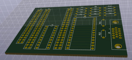
REMEMOTECH r3 can use a daughter board which plugs into its GPIO ports. This provides a centronics connector, port 7 socket, EEPROM socket, and 2nd VGA connector.
This simple circuit diagram produces :-
.
The output voltages are 3.3V and this should be acceptable for devices expecting TTL signals, and the inputs are 5V tolerant.
The intent with the daughter board concept is to make full use of the GPIOs
and enable REMEMOTECH to do as much as is reasonably possible.
Printer
As of REMEMOTECH r3, provision is made for driving a Centronics printer. I imagine it would be hard to source a Centronics printer nowadays, but this feature allows REMEMOTECH r3 to drive a Video Wall.
The daughter board has space for a 2x18 connector
which matches the connector on the MTX motherboard.
Just like with the MTX motherboard, only the top 2x17 pins should be
populated.
Port 7
The REMEMOTECH r3 or later includes support for port 7, courtesy of the daughter board. The socket on the daughter card faithfully reproduces the pinout of the socket on the MTX motherboard, and the strobe features are implemented.
Be sure to study the Altera DE1 manual before connecting the GPIO header
to any homebrew electronics.
VGA monitor support
The SW6 switch determines whether the VDP signal or the 80 column card signal is output to the VGA connector on the Altera DE1.
This is good enough for most purposes, as usually you are interested
in the text, or the graphics.
But occasionally, you might be doing something that would benefit from seeing
both at the same time, such as using VDEB to debug a game.
As of REMEMOTECH r3, whichever signal is not being output to the VGA connector is output to the 2nd VGA connector on the daughter board.
In earlier REMEMOTECH versions,
I used a 40 pin IDE ribbon cable to a VGA breakout board.
This only supported 3 bits per pixel for R, G and B.
And of course, it only supported a 2nd VGA, not all the other connectors.
Misc
REMEMOTECH also has other miscellaneous bits of hardware not found on real Memotechs. Most of these take advantage of bells and whistles on the Altera DE1.
0xc0 to read/write HEX1 and HEX0 seven segment displays
0xc1 to read/write HEX3 and HEX2 seven segment displays
0xc4 to read/write LEDG7 to LEDG0 green LEDs
0xc5 to read KEY2 to KEY0 (REBOOT reads these)
0xc7 to read PS/2 various special number pad keys (REMON reads these)