Back around 1990, a videowall with 4x4 monitors could cost £250,000. From the ashes of Memotech, Geoff Boyd created Memotech Computers Ltd., and produced videowalls at 1/10th of the cost. Information about these can be found on Daves site. There are also good photos at Peter Ketzschmars site.
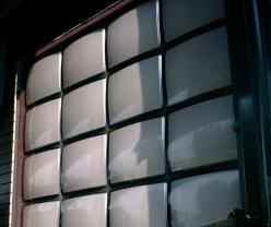
Walls were typically arrays of Barco CRT monitors, and looked a bit like this :-
They were controlled by software that I developed. The first version was a CP/M program that ran on an MTX. The later version was a DOS program that ran on a PC. I still have the source to all the software, and tools to convert between the file formats used. I recently ported the DOS program to Linux.
These programs controlled the videowall hardware by outputting bytes down the centronics port.
Since then, peices of the original videowall black-magic kit have been appearing and making it into peoples collections. But it is difficult and expensive to assemble a complete wall. Also the video format used is the old 15KHz format.
This also makes it difficult to show off the software.
There is a video on youtube showing us trying to get a real videowall to work at Memofest.
The goal is to create a miniature videowall that is massively cheaper, needs far fewer monitors, and works with a more modern video format. The solution needs to be hardware compatible with the original, in that it is controlled by the same bytes sent over a centronics connection.
My design uses a circuit with an analog side that digitises a VGA signal, and a digital side that stores the digitised data, and outputs selected parts of it. It will be possible to populate a second (or more) card(s) with just the digital side, and attach to the first card, thus allowing the same input signal to drive multiple output monitors.
The video resolution will be comparable to the original, but the bits per pixel will be lower. I'm not after video perfection here, just the ability to demo the software with live video of recognisable quality.
The original videowalls were 4x4, 5x5, 6x6 or 8x8 arrays of monitors. Special one-off builds were done for 10x5 (Mecca), 9x8 and 10x8 arrays. Some budget 3x3 walls might have shipped also, but these were just 4x4 walls with fewer framestore cards and monitors (there was never a 3x3 build of the CP/M VW.COM program).
To update a monitor in the Videowall, first send the monitor address, followed by the effect code(s) from the table. All monitor addresses have the top bit set, but none of the codes do.
| Code(s) | Effect |
|---|---|
| 0x20 | Direct |
| 0x21-0x30 | Parts of 4x4 |
| 0x31-0x39 | Parts of 3x3 |
| 0x3a-0x3d | Parts of 2x2 |
| 0x3e | 1x1 |
| 0x3f | Whole |
| 0x40 | *** can't freeze Direct, use 0x5e |
| 0x41-0x50 | Parts of 4x4, frozen |
| 0x51-0x59 | Parts of 3x3, frozen |
| 0x5a-0x5d | Parts of 2x2, frozen |
| 0x5e | 1x1, frozen |
| 0x5f | Whole, frozen |
| 0x6[02468ace] | Colour-washes: Black,Red,Green,Yellow,Blue,Magenta,Cyan,White |
| 0x7e,0x20+N | Special-effect N |
| 0x7e,0x40+N | Special-effect N, frozen |
| 0x7f | Blank |
| 0x00-0x1f
0x6[13579bdf] 0x70-0x7d | *** unused |
To put the input picture on any monitor, use the 1x1 effect. To put any part of the scaled-up picture on a monitor, use one of the 2x2, 3x3 or 4x4 effect codes.
The first walls were 4x4 in size. For sizes above 4x4, such as 5x5, it was not possible to put any part of the 5x5 scaled-up picture on any monitor. Instead, sending the "Whole" effect to a monitor causes the monitor to show its part of the overall scaled-up picture. Each framestore card in larger walls had to have different mapping ROMs, so that code 0x3f produced a different output for each monitor.
The "Direct" effect transferred data directly to the monitor, without digitising and displaying from the framestore. This produced a higher quality picture on that monitor. However, because it wasn't digitised, the monitor could not be frozen. If you attempted to freeze a "Direct" monitor, the software would still send the unfrozen code 0x20, rather than 0x40. I don't know what would have happened if 0x40 had actually been sent to the monitor. To freeze a 1x1 sized picture, use code 0x3e and then freeze it with code 0x5e.
The "Blank" effect looks redundant, given the existence of a black "Colour-wash". However, the first walls didn't have colour-washes, these were added later. I don't know why the colour-washes only used even code values, and I don't know what would have happened if values such as 0x61, 0x63, ... etc. had been output.
The very latest walls introduced the concept of "Special-effects". I'm not sure how many of these (if any) were ever supported in the hardware, and I don't know what they looked like. If they did anything, given how the Videowall hardware worked, it's likely it would be things like change the colours and stretch the picture. From the codes sent, it appears at most 32 could be supported.
The CP/M VW.COM program had special effects 0,1,..,9,A,B,...,Z. Unfrozen special effects W,X,Y,Z overlap frozen special effects 0,1,2,3. There were also 8 special effects named after greek letters, but in the code I have, they never output anything to a monitor.
The MS-DOS VW.EXE program provides for 64 special effects called S01 to S64, and their frozen counterparts. Unfrozen S33 to S64 overlap frozen S01 to S32.
Just to complete the special effect nightmare, the tools I have that convert from VW.COM to VW.EXE format map the greek letters to S37 to S44, but when converting in the other direction there is no such mapping!
Once all the monitors have been updated, the MS-DOS VW.EXE program sends the value 0xff, although the CP/M version does not. There is a comment in the code saying "/* Or whatever code Geoff chooses */", suggesting this was never fully implemented. It'll be interpreted as a monitor address, and because it isn't followed by any effect code(s), will be ignored. I beleive this was intended allow synchronized updates to large walls: you'd send a code to each one, which wouldn't take effect until the 0xff was sent, and then they all responded in unison. Realistically this would have needed other code(s) to tell the wall to enter and leave synchronized update mode, and some instructions the user could use to send the codes.
"Special-effects" and the "Synchronized update" mechanism will be ignored, but everything else is supported with the following caveats...
A single Videowall framestore card can support a single monitor (ie: 1x1), or pretend to be a 2x2, 4x4 or 8x8 array of monitors. A framestore is told which NxN part of the larger 8x8 wall space it covers. Size and offset are controlled by configuration jumpers, as per :-
| 7 | 6 | 5 | 4 | 3 | 2 | 1 | 0 | Description |
|---|---|---|---|---|---|---|---|---|
| 0 | 0 | y | y | y | x | x | x | 1x1 at yyy,xxx |
| 0 | 1 | y | y | x | x | 2x2 at yy0,xx0 | ||
| 1 | 0 | y | x | 4x4 at y00,x00 | ||||
| 1 | 1 | 8x8 at 000,000 |
A monitor at position (x,y) responds to address 0x80+y*0x10+x. In addition, it will also respond to address 0x88+y*0x10+x. ie: I don't check bit 3 of the monitor address. I may one day choose to use the PMOD header to supply the value to check against.
The "Whole" effect produces the appropriate portion of an 8x8 scaled image. ie: the full wall size is 8x8. I may one day choose to use the PMOD header to encode "whole" wall size and offset, allowing some of the other sizes.
"Direct" is treated the same as "1x1". The video is always digitised and displayed from a frame buffer. First, there is no analog video path bypassing digitisation. Second, when this Videowall hardware emulates multiple monitors, it would be impossible anyway. As a minor consolation for the loss of video quality, if code 0x40 was actually sent to the wall, video will be correctly frozen.
Odd numbered "colour-wash" codes such as 0x61,0x63,...,0x6f produce shades of grey.
Unsupported codes produce an orange colour wash.
In theatre "it's all done with mirrors", but in Memotech Videowalls "it was all done with lookup-tables".
Given we have an effect, we need to know how to map the VGA coordinates to make framebuffer coordinates.
| Code | Effect | S | oX | oY |
|---|---|---|---|---|
| 0x20 | Direct | 1 | 0 | 0 |
| 0x21 | 4x4(0,0) | 4 | 0 | 0 |
| 0x22 | 4x4(1,0) | 4 | 1 | 0 |
| 0x23 | 4x4(2,0) | 4 | 2 | 0 |
| 0x24 | 4x4(2,0) | 4 | 3 | 0 |
| 0x25 | 4x4(0,1) | 4 | 0 | 1 |
| 0x26 | 4x4(1,1) | 4 | 1 | 1 |
| 0x27 | 4x4(2,1) | 4 | 2 | 1 |
| 0x28 | 4x4(2,1) | 4 | 3 | 1 |
| 0x29 | 4x4(0,2) | 4 | 0 | 2 |
| 0x2a | 4x4(1,2) | 4 | 1 | 2 |
| 0x2b | 4x4(2,2) | 4 | 2 | 2 |
| 0x2c | 4x4(2,2) | 4 | 3 | 2 |
| 0x2d | 4x4(0,3) | 4 | 0 | 3 |
| 0x2e | 4x4(1,3) | 4 | 1 | 3 |
| 0x2f | 4x4(2,3) | 4 | 2 | 3 |
| 0x30 | 4x4(2,3) | 4 | 3 | 3 |
| 0x31 | 3x3(0,0) | 3 | 0 | 0 |
| 0x32 | 3x3(1,0) | 3 | 1 | 0 |
| 0x33 | 3x3(2,0) | 3 | 2 | 0 |
| 0x34 | 3x3(0,1) | 3 | 0 | 1 |
| 0x35 | 3x3(1,1) | 3 | 1 | 1 |
| 0x36 | 3x3(2,1) | 3 | 2 | 1 |
| 0x37 | 3x3(0,2) | 3 | 0 | 2 |
| 0x38 | 3x3(1,2) | 3 | 1 | 2 |
| 0x39 | 3x3(2,2) | 3 | 2 | 2 |
| 0x3a | 2x2(0,0) | 2 | 0 | 0 |
| 0x3b | 2x2(1,0) | 2 | 1 | 0 |
| 0x3c | 2x2(0,1) | 2 | 0 | 1 |
| 0x3d | 2x2(1,1) | 2 | 1 | 1 |
| 0x3e | 1x1 | 1 | 0 | 0 |
| 0x3f | Whole |
If the effect name is NxN(x,y), then x and y reflect which part of the NxN enlarged picture is required.
In the case of "Whole", the scale factor is 8, and oX and oY reflect the monitor position.
VGA coordinates: vX in [0..639], vY in [0..479].
Framestore coordinates: fX in [0..319], fY in [0..239].

fX = (oX*640+vX)/S / 2
fY = (oY*480+vY)/S / 2
It was the equivalent of this mapping which was stored in EPROM. For each of the 32 effects, for each of the possible vX coordinates, the fX was stored (and also for vY and fY). The mappings weren't quite as described, as they made allowances for the thickness of the edges of the monitors, although I won't worry about this. A naive implementation, (naively) assuming perfect resource allocation, needs 17 x RAMB18E1, which blows the budget.
I'll simply use some combinatorial logic in the FPGA,
supported by a lookup table of x/3.
Video capture hardware
The board is made up of an
analog part, a
digital part, and a part which produces regulated
power.
Analog
When I talk about VGA, I am talking about 640x480 at 60Hz. Any form of super VGA is not supported - the pixel rates would be too high, and the amount of memory to store a frame would be too high. This is a hobby project on a hobby budget.
The card takes in a VGA video signal and uses 3 AD8041 op-amps to convert the 0.0-0.7V VGA to 3.0-2.0V. I used the Designing Gain and Offset in Thirty Seconds Application Report by Texas Instruments to calculate resistor values suitable for the desired transfer function. Note that the design uses a trimmer between two of the resistors, so I can tune the amplication.
The 3.0-2.0V is then fed into 3 AD9057 flash ADC chips to digitise the video signal.
Unfortunately these chips are SSOP-20, ie: surface mount. I watched several videos on the internet on how to do this, bought some fine gauge solder and a flux pen and had a go. Utter disaster - solder bridges, damaged board and chip legs! The biggest problem is clearly my eyesight, so I've bought an AmScope 10x disecting binocular microscope (£200). With this, a new soldering iron tip, lots of flux, some wick for mistakes, and some practice attempts with sacrificial SSOP-20 chips, I was able to do a reasonable job.
AD9057s can produce a new sample at 40MSPS or better, which is better than the 25MHz VGA pixel rate. The clocking will come from the FPGA on the digital part of the board. The FPGA will latch the digital outputs of the ADCs at the same time, and I've arranged that the digital output voltage of the ADCs is 3.3V, so that it can be directly fed into the FPGA module, without going through any kind of level shifting (which would add delays).
The AD9057 datasheet says "The MagAmp/Flash architecture of the AD9057 results in three pipeline delays for the output data", though from the following diagram I read that if I raise the ENCODE signal at t=0, to read sample N, I'll be sampling at t=4 :-
There is guidance in ADC datasheets about placement of decoupling capacitors, the use of ground planes, and separate power supplies for the analog and digital sides of things. I'm not able to fully follow this guidance, so I expect noise in the output. However, although the capture card outputs 8 bits of red, green and blue, for this project, the framestore card(s) will only be able to handle the top 3 bits of each. Its a calculated risk that the noise remains in the lower 5 bits. I've had to redesign the board to include regulated power, smoothing capacitors, and a ground plane fill, to try to minimise noise.
There are some 0Ω resistors in the design.
This is a trick to get the desired behaviour out of Kicad and Freeroute.
These connect the power (as it enters the board) to the the 0V, 5VA and 5V
supplies used in the board.
This allows me to keep the analog and digital 5V lines apart (which is a
recommended best practice when ADCs are involved).
Thanks to Mark Kinsley for explaining this to me at Memofest 2018.
Digital
This part of the board uses
I considered using a Mercury Micronova, but its XC3S200A FPGA only has 28KB BRAM and its 512KB SRAM has 10ns access time, for the same $89.
I use a CMT to fabricate a 50MHz clock from the 12MHz clock on the Cmod. You have to multiply to get into the MMCM VCO 600-1200MHz frequency range, and then divide. A multiplier of 50 and divisor of 12 does the trick.
The FPGA has many pairs of input pins which can be used as differential pairs, or the +pin may be used as a clockable input. Some are accessible as Cmod pins PIO03, PIO05, PIO36, PIO38, PIO46, PIO47. I use PIO36 as the main clock input.
I had also planned to use PIO05 for the centronics STROBE_n. The strobe pulse will be 1.5+/-0.5us, ie: 1-2us. But not all hardware meets these constraints - I also know that some PC software simply does two successive OUT instructions to cause the strobe pulse, and although this would have met timing constraints with older PCs, with modern fast PCs this could mean a very short pulse. The plan was that by using a clock capable FPGA input, I can trigger on the edge, however short the pulse is. However, this caused issues relating to crossing clock domains, so I settled on sampling strobe at 50MHz, looking for a high to low transition. I had to filter out glitches in order to get reliable results. As a result, the shortest STROBE_n pulse I recognise is 60ns long.
Within the FPGA, the BRAM can be arranged 9 bits wide (8+parity), which is handy because I store 3 bits red, 3 bits green and 3 bits blue per pixel. There is theoretically space for 204800 x 9 bit pixels.
A 640x480 frame requires 307200 pixels, which is too big to fit in BRAM. What's worse, is that I need space to store 2 frames in order to be able to double buffer the video and avoid tearing effects where the frame buffer is being displayed as it is being updated. A 320x240 frame requires 76800 pixels, and 2 frames need 153600, which fits. When capturing the video, the hardware averages each 2x2 group of pixels and stores that.
The FPGA has 100 RAMB18E1 BRAMs, and by exploiting the parity bits as an extra bit of data, I should be able to get away with using 80 BRAMs. As it turns out, Vivado optimizes for speed, rather than minimum resource usage, and the minimum I seem to be able to get away using is 90. Even this requires me to divide the 320x240 frame into 5 x 64x256. The only way to do better is to explicitly instantiate the RAMB18E1s and the address decoding around them, or use the memory core generator.
The external SRAM is used to support freeze-mode. Whenever data is output to a monitor, a copy is written to SRAM, but if the monitor is frozen, then going forwards that SRAM copy is output instead of from BRAM. As the external SRAM is 512K x 8bit, only the top 2 bits of blue will be saved and used in freeze-mode.
Jumpers exist so that signals generated by the Cmod are routed to the capture side of the board, and back over the centronics cable. If an additional board(s) is attached (with only the digital side populated), this will not have these jumpers populated.
For debugging only, I accept the videowall protocol bytes over the virtual serial port (115200 baud, no parity), which traverses the USB connection, but this implies power will be coming from the USB, and so power should not be applied from anywhere else. A good degree of testing was possible using :-
$ stty -F /dev/ttyUSB2 115200 raw
$ memu -s -v -prn-file /dev/ttyUSB2 VW.COM
I got misled reading the FT2232H datasheet. Ignore the stuff about all the various modes and waveforms possible, and the stuff about dual channels and source and destination bits - in practice just create a waveform with start bit (low), 8 data bits (least significant first) and stop bit (high).
Button 1 toggles between digitising the testcard and the input video stream. As video digitisation is pipelined in the AD9057's, and takes 4 clocks, the testcard signal is internally delayed by the same amount.
Button 2 initialises the wall to one of 4 standard configurations. ie: all "1x1"s, a 4x4 array of "2x2"s, a 2x2 array of "4x4"s or all monitors showing their part of the "Whole".
The software I wrote to drive the wall has the optimization that if you set an effect that is already on display, no effect code is sent. You can cause odd results by pressing button 2 - the software might think the right effect is on display, despite the fact you changed it.
Resources for Working with Cmod A7 :-
.bin file
so that programming can be persistent
I thought Eclipse was bad when it came to software media size!
Power
This part of the board uses :-
There are also decoupling capacitors elsewhere on the board.
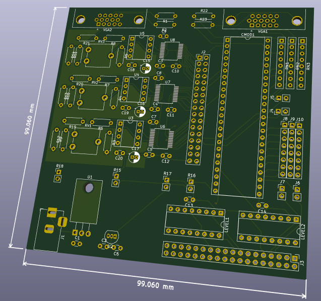
Circuit
I designed this circuit, which when placed and routed, and then manufactured, looks like this :-
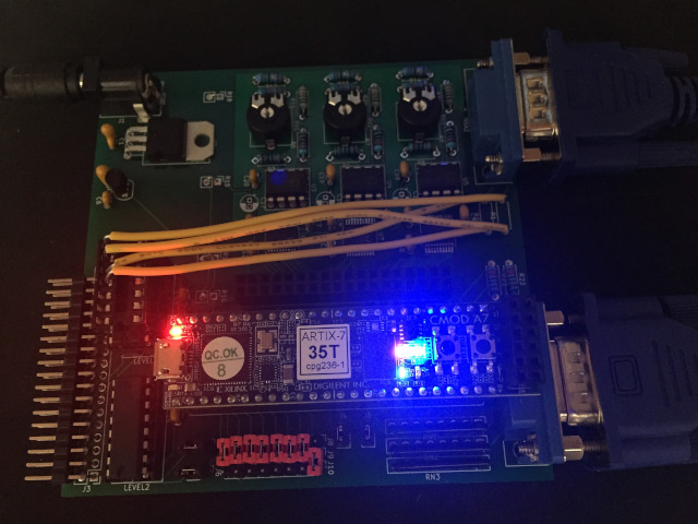
The yellow wires shatter any illusion that I know what I am doing. In the circuit at present, there is no level shifting of the 5V sync signals from the input VGA, down to 3.3V before feeding into the FPGA. The FPGA inputs are not 5V tolerant, and so I'll damage the FPGA. As a workaround, I pass the sync signals through unused portions of one of the 74HC4050 level shifters, before using them.
The remaining unaddressed issue is that these level shifters are not fast enough. This will likely manifest itself as variability in when the left edge of the image is detected, producing slight wobbling and zigzag like effects on vertical edges. These problems are seen.
An alternative might be to use resistors to create a voltage divider,
but board capacitance and the short transition times required (we're running at 25MHz)
will probably make this approach worse.
BOM
| Area | Part | Quantity | Source(s) | Cost |
|---|---|---|---|---|
| General | PCB 2 layer, green, 10cm x 10cm max, 1.6mm HASL | 1 | iteadstudio | $23 / 10 = $2.30 |
| Analog, VGA in | VGA DE15 Female connector | 1 | eBay? | £4 |
| Analog, VGA in | 220Ω resistors | 2 | ||
| Analog | AD8041 op-amp | 3 | Mouser or Farnell | £16 |
| Analog | AD9057 flash-ADC | 3 | Mouser or Farnell | £15 |
| Analog | 2.2KΩ trimmer potentiometer | 3 | Digikey or Mouser | £2 |
| Analog | 10KΩ resistors | 6 | ||
| Analog | 8.2KΩ resistors | 3 | ||
| Analog | 5.6KΩ resistors | 3 | ||
| Analog | 75Ω resistors | 3 | ||
| Analog, decoupling | 0.1uF capacitor | 12 | ||
| Analog, decoupling | 10uF electrolytic capacitor | 3 | ||
| General, board stacking | 17x2 female header | 1 | ||
| Digital | Cmod A7-35T | 1 | Digilent or Digi-Key or Element14 or Farnell | $89 = £70 |
| Digital | 48 pin DIP socket | 1 | Farnell | £1 |
| Digital, FPGA config | 8x1 headers | 3 | ||
| Digital, FPGA out | 2x1 headers | 4 | ||
| Digital, centronics in | 18x2 header (right angled) | 1 | ||
| Digital, centronics in | 74HC4050 level shifters | 2 | ||
| Digital, centronics in | 16 pin DIP socket | 2 | ||
| Digital, VGA out | 7 bussed 2.2KΩ resistor network | 3 | ||
| Digital, VGA out | 220Ω resistors | 2 | ||
| Digital, VGA out | VGA DE15 Female connector | 1 | eBay? | £4 |
| Digital, decoupling | 0.1uF capacitor | 2 | ||
| Power | Barrel Jack, 2.5mm | 1 | Mouser or Farnell | £2 |
| Power | L7805 regulator | 1 | ||
| Power | L78L33 regulator | 1 | ||
| Power, smoothing | 0.33uF capacitors | 2 | ||
| Power, smoothing | 0.1uF capacitors | 1 | ||
| Total | <£120 | |||
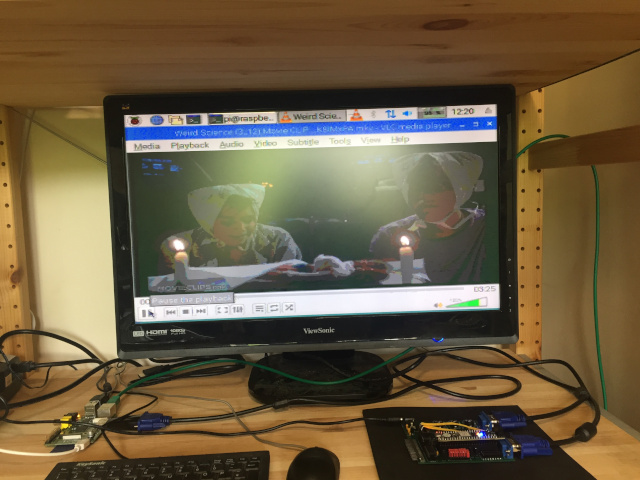
It can be quite hard to find devices that output VGA 680x480. Obviously things like REMEMOTECH and REMEMOrizer do it, but these only output 15 distinct colours. I'd like to show off something with a bit of colour/shade gradation, such as video from youtube. Increasingly, laptop and desktop graphics cards/drivers tend to support a minimum resolution of 800x600, so this is also a dead end. My solution was to configure a Raspberry Pi to output 640x480. Chrome runs like a dog on the Pi, so rather than play video from youtube, it's better to download a video to it and use VLC.
I can use a real MTX to drive the VGA Videowall. The MTX should have REMEMOrizer, or a CFX, and a disk with the VW.COM software on it. With a suitable ROM card, and some messing around with boot ROMs, the sofware could be made to run on an MTX with no real disks, as happened back in the day.
It is possible to drive the wall from a PC, using USB parallel adaptor, such as the Belkin F5U002, which unfortunately are quite hard to find. I bought one from eBay, blew it up, then bought another, and haven't seen any more for sale since.
If I had a PC running MS-DOS, I would run the VW.EXE software to drive the wall, but unfortunately, I don't have one. Instead, I ported VW.EXE to Linux, and can run this version instead. This was quite an undertaking, as I had not done a very good job separating platform independent code from MS-DOS specific code in the original codebase. In my defence, platform independence wasn't really a requirement back then.
The Linux software can use the parallel port. You can also tell it to use USB to talk directly to the CMod A7. If you do this, refer to the warning above regarding USB and power.
As mentioned earlier on this page, it is also possible to run VW.COM in MEMU, redirecting the printer output to a USB device on Linux.
Here are some videos showing how good the output is, first with a grayscale testcard, then using a clip from Weird Science.
This design can be downloaded from
http://www.nyangau.org/vgavw/vgavw.zip.
The author of the design and this documentation is Andy Key
(email andy.z.key@googlemail.com).
{{{ Andy